Chapter 4. On-line Spike sorting
Legend:
|
1
|
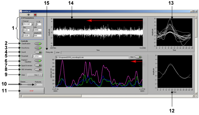
- Group Control of Input/Output parameters
|
|
2
|
- “Classification” control button to switch “ON” and “OFF” classification algorithm. “ON” is default value.
|
|
3
|
- “Waveform” control button to to switch “ON” and “OFF” visualization of waveforms in indicators 12 and 13. Switching “OFF” may slightly improve overall classification performance on some slow computers. “ON” is default value.
|
|
4
|
- “Sound” control button to switch “ON” and “OFF” the generation and reproduction of the sound (both clicks or original signal, see 6) through line-out of the computer board. “OFF” is default value.
|
|
5
|
- Actual threshold level for spike detection algorithm.*
|
|
6
|
- “Original/Classified” control button to reproduce Original signal picked up by electrode or Clicks regarding classified waveforms though line-out of computer sound board. “Classified” is default value.
|
|
7
|
- “Signal Inversion” control button to switch “ON” and “OFF” the inversion of the input signal.*
|
|
8
|
- “HDD streaming” to switch “ON” and “OFF” data storage to HDD of the computer with a filename.dat indicated above Flow Chart indicating single unit activity.
|
|
9
|
- Ring menu selecting of the isolated unit to be acoustically reproduced and visualized in 12.
|
|
10
|
- Information panel displaying number of clusters and features used*
|
|
11
|
- “STOP” control button to close current window and stop online monitoring.
|
|
12
|
- Graph indicating spike shapes that were successfully passed classification procedure and satisfied the parameters of class selected by 9.
|
|
13
|
- Graph indicating all spike shapes extracted at the current moment of time.
|
|
14
|
- Moving chart indicator displaying raw signal.
|
|
15
|
- Flow Chart indicator displaying current firing rate of isolated and classified single units
|
Note: * - settings are the same as determined automatically by “TEST” procedure (see Chapter 2 - Figure 2, for details).
